


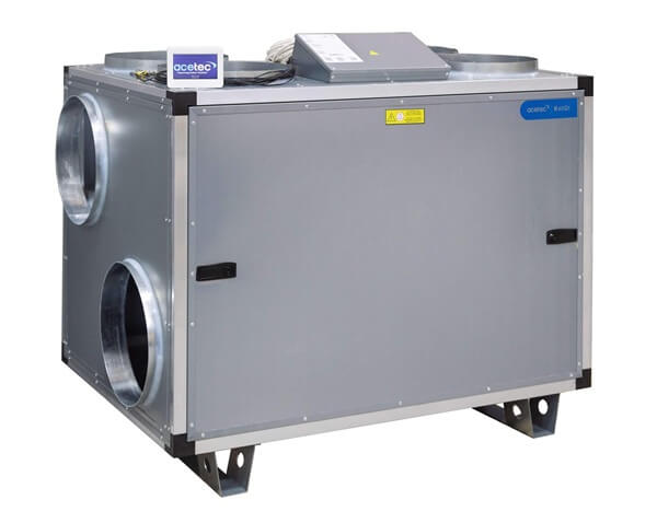
EvoAir R40 is an air handling unit with integrated control, rotary heat exchangers, EC fans and efficient filters. The unit recovers heat and cold with up to 87% efficiency and is designed for energy efficient operation with low internal pressure drops. The design allows top, side or L-connection.
HRV Ventilation Unit
EvoAir R40
Article number:
33040
Made in Sweden
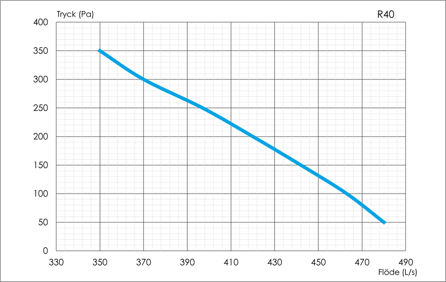
Performance


Brochure
Art. no.: 33040
•
EAN: 7350070006215
Advantages of the programme
- For offices, schools and business premises
- Flexible connection: top, side or L-connection
- Rotary heat exchanger, efficiency up to 87%
- Radial fans with EC motors
- EvoControl Touch and cloud service
- Filter class ePM1 55%
Full product information is available at www.acetec.se
EvoAir ventilation units are manufactured and quality assured in Älvsbyn, Sweden.
Technical data
| Specification | Value |
|---|---|
| Connection options | Side/top |
| Flow range (l/s) | 100 to 500 |
| Customisable H/V | Yes |
| Control equipment | EvoControl Touch |
| Type of heat exchanger | Rotating |
| Placement | Floor |
| W x H x D (mm) | 1120 / 883 / 780 |
| Weight (kg) | 133 |
| Duct connection (mm) | 8 x 315 |
| Fan power (W) | 2 x 530 |
| Connection voltage (V) | 1 x 230 |
| Hedging (A) | 10 |
For technical advice or to request a quote, please contact sales@acetec.se
Acetec
•
Product catalogue
•
EvoAir R40
Pressure and flow diagrams
Flexible connectivity options

The innovative design of the unit allows for several different connection options. Supply, extract, outdoor and exhaust air each have two connections. For example, both exhaust air outlets can be used if two connections for exhaust air are required. Supply air, on the other hand, can only be connected to one spigot, as the duct battery can only be fitted to one supply air duct.
The same unit can therefore top connected, laterally connected or L-connectors. An example is an installation where only the exhaust air is connected at the top while the other ducts are connected at the side.
The connections that are not used are covered with the supplied cover.
Acetec
•
Product catalogue
•
EvoAir R40
Product dimensions

| Designation | Dimensions (mm) |
|---|---|
| A | 1120 |
| B | 780 |
| C | 103 |
| D | 105 |
| E, F, G, H | 218 |
| I | 208 |
| J | 364 |
| K | 208 |
| L | socket 315, protrusion 40 |
Acetec
•
Product catalogue
•
EvoAir R40
See designations in the illustration above.
Acetec
•
Product catalogue
•
EvoAir R40
Installation Instructions
Art. no.: 33040
•
EAN: 7350070006215
General
Installation and commissioning shall be carried out by qualified personnel with the necessary professional knowledge to ensure correct operation.
Suitable location is in a fan room, storage room or similar space. The unit can also be placed in a cold room. Delivery is in right-hand version but can easily be changed to left-hand version.
The unit is equipped with six connection sockets, four of which are used. The connections used depend on the connection variant selected (see next page). The two connection sockets that are not used are fitted with the covers supplied.
The unit has inspection hatches on both sides to allow multiple connection options. The heating coil and possibly the cooling coil are placed in the supply air duct.

The minimum service space in front of the inspection hatch is 950 mm, to enable the replacement of all components.
Flow metering outlets
For each fan there are pressure measurement sockets for flow measurement:
- R25 = 2000-2-2945 / 52
- R40 = 28004-2-4013 / 21,4
- R50 = 28004-2-4013 / 21,4
- R70 = 31002-2-4013 / 25,8

There are two measuring sockets under the metal cover.
Heating and cooling battery
The electric battery is installed in the supply air duct and is provided with its own power supply. The electric battery is interlocked with an internal flow switch.
Water coil kit for heating and cooling contains duct coil, valve actuator, control valve and anti-freeze sensor. Supplied complete with connection instructions.
Acetec
•
Product catalogue
•
EvoAir R40
Determining connection variants
Right variant = Supply air to the right (delivery version)
- Parameter 100 is set to the upper position on delivery, which means that the right (upper) fan is the supply air fan.
- Decide which connections to use at the top and side respectively. Other connections are covered with the supplied cover.
- Install duct coil for heating and possibly cooling in the supply air duct and possibly damper in the outdoor air or exhaust air duct. The cooling coil must be installed in a horizontal duct due to condensation traps.
- Install the labelled temperature sensors in each duct: supply, extract and outdoor air.

- Green colour = Outdoor air
- Blue colour = Supply air
- Gul = Exhaust air
- Brown = Exhaust air
Left variant = Supply air to the left (change parameter 100 to lower)
- Green colour = Outdoor air
- Blue colour = Supply air
- Gul = Exhaust air
- Brown = Exhaust air
- Change parameter 100 to lower position, which means that the left (lower) fan is the supply air fan.
- Decide which connections to use at the top and side respectively. Other connections are covered with the supplied cover.
- Install duct coil for heating and possibly cooling in the supply air duct and possibly damper in the outdoor air or exhaust air duct. The cooling coil must be installed in a horizontal duct due to condensation traps.
- Install the labelled temperature sensors in each duct: supply, extract and outdoor air.
Acetec
•
Product catalogue
•
EvoAir R40
Commissioning
When commissioning, air flows must be adjusted so that the exhaust air flow is 10-15% higher than the supply air flow (negative pressure) for safe operation. Applies to all operating modes.
Important to consider when installing
- Installation and commissioning shall be carried out by a person with sufficient professional knowledge to ensure proper functioning.
- If the system is not commissioned immediately, all duct connections should be sealed inside the unit to prevent moist or cold air from entering and causing moisture damage.
- All operating modes shall be adjusted (Spruce, Comfort and convenience and Forcing).
- The control panel should be positioned so that the user has good access and overview in the event of an alarm.
- The user/manager of the installation shall be informed of the location of the control panel and its functions.
- The installer shall hand over the manuals and the guarantee certificate to the user/manager of the installation.
- The product must be registered at www.acetec.se for the guarantee to apply.
- Original filters must be used during the warranty period for the warranty to be valid.

EvoControl Touch
Control is via a 4.3-inch colour panel with touch display, providing a clear and intuitive user experience. The system has a wired network connection for stable communication and also offers a cloud solution with a responsive design that automatically adapts to mobile phones, tablets or computers. Advanced functionality allows you to control the indoor climate with high precision, customise operation as needed and monitor the system in real time.

Components
EvoControl Touch consists of the following parts:
Display

4.3” colour panel with capacitive touch.
Main card

- Fuse 5x20mm, 200mAT, 230VAC
- RJ45 network socket
- Battery CR3225
- USB connector
Included
- 15 m cable 4×0.25 mm² (max. length 50 m)
- 4 plastic spacers
- Screw (for surface mounting)
Installation of the display
The touch panel should be installed in a warm, weather-protected and dry area where it is clearly visible and easily accessible to the user. Avoid placing it in areas with high humidity or risk of condensation.
- Push the frame away from the display by holding the edges of the frame and pressing lightly on the display.
- Unscrew the four screws on the sides of the display.
- Fit the wall plate over any existing wall socket or on the outside using plastic spacers and screws.
- Connect the cable to the terminal block on the display.
- Cables can be released from the connector by inserting an object (e.g. a small needle) into the gap above the cable.
- Check that the cables are securely connected and that no strands are sticking out!
Would you like a more detailed description with pictures? Click on the link or scan the QR code at the top. See section 6.
Acetec
•
Product catalogue
•
EvoAir R40
EvoControl Touch display menu
Menu 1

- Heat recovery active / Reheating active / Cooling active / Defrosting active
- Temperature setting for active operating mode
- Activation of operating mode
- Indication of external operating mode, air quality control, fire, stop
- Various alarms (see alarms in technical manual), cloud service, network
- Go to Menu 2
- Activation of ECO function (parameter 400 must be activated)
- Activation of sleep mode (times must be set); to deactivate, press and hold the button for 2 seconds.
- Activation of overpressure function (fireplace function)
- Activation of forced hours
- Stop active, to activate hold button for 2 seconds / Other operating mode active or unit in standby (timer, external control)
Menu 2

- Display of measurement values in real time
- Time menu
- Alarm acknowledgement and history
- Service menu. PIN code 1 required
- Settings menu. PIN code 1 for normal settings and PIN code 2 for advanced settings required.
- System information
Acetec
•
Product catalogue
•
EvoAir R40
Quick guide to EvoControl Touch
This quick guide applies to standard units without accessories. For complete technical instructions, use the link on the first page of the manual or scan the QR code.
Step 1)
Press the button Menu button:
Step 2)
Press the button Preferences:
Step 3)
Enter the authorisation code 6374 for basic settings or 8990 for advanced settings and press Enter.
Step 4)
Press the button Fan:
Step 5)
- Use the arrow keys to navigate to the parameters you want to change.
- Use minus and plus to change the value.
- Save the value with the button Save (only visible when the value is changed).
- Pressures Back to go back to the start menu.
Interface step 1

Interface step 2

Interface step 3

Interface step 4

Interface step 5

Acetec
•
Product catalogue
•
EvoAir R40
Wiring Diagram
Art. no.: 33040
•
EAN: 7350070006215

Acetec
•
Product catalogue
•
EvoAir R40
Acetec
•
Product catalogue
•
EvoAir R40
Operation and Maintenance
Art. no.: 33040
•
EAN: 7350070006215
Before working with the unit
Only authorised personnel should operate and service the unit. This instruction applies to all units and describes operating principles, maintenance, troubleshooting and safety measures. The aim is to ensure a long service life, high operational reliability and energy-efficient operation.
General about the unit
The unit is intended for comfort ventilation and air treatment. Operating temperatures, humidity limits and environmental requirements vary depending on the model. The unit should be located in a dry and easily accessible environment. Avoid operation in corrosive or explosive environments.
Service intervals and inspection schedule
Carry out servicing at least twice a year or more often at high load. Supplement with intervals for specific components as below:
- Filter byte: every 3-6 months or after a defined number of operating hours.
- Checking seals and mouldings: each service.
- Checking fan bearings and motors: annually.
- Cleaning of rotor or heat exchanger: annually.
- Control of sensors and control systems: annually.
See service procedure (cleaning, dismantling, etc.) on the next page.
Acetec
•
Product catalogue
•
EvoAir R40
Service procedure
- Switch off the power to the unit via fuse or plug before servicing.
- Secure the unit against accidental re-connection during work.
- Wait until all moving parts have come to a complete stop before starting work.
- Use personal protective equipment such as protective gloves and goggles. When working with dust, wear a respirator.
- Mark the unit with a warning sign during servicing.
- Open inspection hatches or panels (e.g. loosen screws with a suitable Allen key).
- Take old filters straight out of their mounts.
- Vacuum the inside and clean surfaces with a mild detergent (avoid strong solvents).
- To facilitate internal cleaning, fans fitted with electrical connectors can be removed from the unit (document electrical connections before dismantling components).
- If necessary, clean the rotor or heat exchanger unit according to the recommended method.
- Check seals, gaskets and mouldings.
- Fit new filters and reassemble components correctly. Original filters can be ordered at www.acetec.se
- Check that everything is secure and close the hatches.
- Reinstall all guards and ensure proper operation before putting the unit into service.
After completion of the service
- Reconnect the power.
- Switch on the unit.
- Check air flow, fan speed and pressure balance.
- Review alarm logs and any error indications.
- Listen for sounds or vibrations.
- Check operation in different modes (high/low, bypass, etc.).
Acetec
•
Product catalogue
•
EvoAir R40
Troubleshooting and malfunctions
In case of a malfunction, check the following points before contacting customer support:
- No operation: check fuses, power supply, plug.
- Low airflow: check filters, fan motors and belt tension.
- Abnormal sound or vibration: check fasteners, bearings and balance.
- Error indication from sensors: check the cable, sensor and connections.
- Control system failure: check communication and parameters.
Documentation and spare parts
All service measures must be documented in a service log with the date, signature and measures taken. Only use original spare parts and original filters to maintain the warranty.
Filters, fans and other components can be ordered at www.acetec.se
Technical Data Sheet
Art. no.: 33040
•
EAN: 7350070006215
| Specification | Value |
|---|---|
| Terms and conditions of guarantee | AG20 |
| EC | Yes |
| EcoDesign | Yes |
| EuroVent | No, it is not. |
| Control equipment | EvoControl Touch |
| Cloud service | Yes |
| Flow range (l/s) | 100 - 500 |
| Cooker hood (accessory) | No, it is not. |
| CO2 sensor room (accessory) | Yes |
| Connection options | Side/top |
| Customisable H/V | Yes |
| Placement | Floor |
| Installation in a cold room | Yes |
| Duct connection (mm) | 8 x 315 |
| Type of heat exchanger | Rotating |
| Power, fan, nom (W) | 2 × 530 |
| Connection voltage (V) | 1 × 230 |
| Hedging (A) | 10 |
| IP class | IP21 |
| Built-in electric battery EV | No, it is not. |
| Electric battery kit EV (accessory) | Yes |
| Electric battery kit FV (accessory) | No, it is not. |
| Water battery kit (accessory) | Yes |
| W x H x D (mm) | 1120 / 883 / 780 |
| Weight (kg) | 133 |
| Filter class | F7 |
| Coatings / Materials | Magnelis |
| Corrosion class | C4 |
Acetec
•
Product catalogue
•
EvoAir R40
Date of issue: 10 March 2026