


EvoDry RCF 20 G1 ÄH


Brochure
EvoDry RCF 20 G1 ÄH (Älvsbyhus) is a desiccant dehumidifier developed for the effective management of moisture problems. It has a dehumidification capacity of up to 17.5 litres per day at 20°C and 60% RF. The product is CE marked and covered by the AG20 warranty, providing peace of mind regarding performance and durability.
EvoDry RCF 20 G1 ÄH is developed with a focus on energy-efficient operation and is suitable for spaces up to 300 m³. Modern technology combined with high user-friendliness makes installation and control easier. The supplied control panel displays the operating status, current humidity and any climate alarms and allows easy adjustment of operating settings.

EvoDry dehumidifiers are manufactured and quality assured in Älvsbyn, Sweden.
Typical application areas
- Crawl space: EvoDry RCF dehumidifiers effectively reduce humidity and prevent mould. The slight negative pressure created reduces ”earthy odours” and can contribute to slightly warmer floors. The external display gives full control over the climate of the space.
- Cold wind: In cold attics, moisture and condensation can cause mould growth - especially after window replacement or additional insulation in older houses. With an RCF dehumidifier, the relative humidity is kept at a level where mould cannot develop.
- Garage: Cold garages often experience high moisture loads from vehicles, doors and temperature differences. An RCF dehumidifier keeps the air dry and protects the building, fittings and tools from harmful moisture levels.
Technical data
| Specification | Value |
|---|---|
| Suitable up to (m³) | 300 |
| Control panel | Yes |
| Wet air flow (m³/h) | 27 / 42 |
| Dry air flow rate (m³/h) | 247 / 295 |
| Capacity at 20°C/60% RF (l/24h) | 17,5 |
| Sound level (dBA) | 56 |
| Hedging (A) | 10 |
| Power, fan, nom (W) | 88 |
| Power, at dehumidification (W/h) | 900 |
| W x H x D (mm) | 370 / 255 / 380 |
| Weight (kg) | 12,6 |
Capacity diagram

Components included
- Desiccant dehumidifier EvoDry RCF 20 G1 ÄH
- Control panel MPO-01 with EDC 01 control
- Modular cable, 15 m
- Outlet plate
- Wet gas hose
- Dry air ducts, 3 x 15 m
- Hose clamps, 5 pcs
- Spare filter, 9 pcs


Packaging in cardboard box is saved for installation. Used for setting up the dehumidifier.
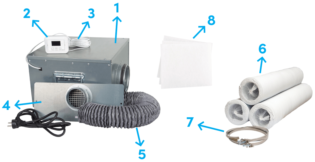
Ensure that all the above components are present when opening the package.
Installation Instructions
Preparation
Clean and clear the soil of organic material, such as plants, leaves and construction debris.
For best performance and lowest energy consumption, the space should be made as dense as possible. Cover the ground with age-resistant plastic sheeting, overlapping by about 50 cm. For optimum tightness, it is recommended that the plastic is fixed to the bottom edge of the foundation beam with insulating washers or with a batten and nail plug. Fold the plastic in half against the beam or foundation wall and stretch it slightly between each fixing point. Seal all valves - except the one used for the wet gas hose.

Assembly
The dehumidifier must be installed by a qualified person in accordance with the installation instructions. Ensure that the installation site fulfils the requirements for operation and service space before starting the installation.
The dehumidifier is intended for installation indoors only or in a weather-protected space. It must not be installed in environments with aggressive or explosive gases, and must not be exposed to water splashes or immersed in water. The dehumidifier is placed in the space to be dehumidified. The wet gas hose (80 mm) is led out of the served space and connected to the outlet plate mounted on the outside of the wall. The hose must not exceed a length of 1.5 metres.
A duct or hose can be fitted to the spigot of the dehumidifier to spread the dry air evenly in the space. Also the suction side, where the humid air is taken in, can be connected with the accessory process air blast. Electrical connection is via cable with plug to earthed socket, 1×230 V, with own fuse 10A slow blow.
See step-by-step installation instructions on the next page.
Small condensation hole in wet gas hose during installation
The wet gas hose should be kept as short as possible to avoid condensation in the hose. The hose can also be insulated externally or, if possible, mounted with a slope towards the outlet plate.

Alternatively, a small condensation hole (about 3-5 mm) be made at the lowest point of the hose, which should be positioned lower than the wet gas connection of the dehumidifier, so that any condensation can drain out instead of flowing back into the dehumidifier. The hole acts as a "water trap" and does not affect the capacity of the dehumidifier, as only very small amounts of precipitated moisture are involved.
Step-by-step installation instructions
- Place the dehumidifier in an elevated position, for example on a leca block, an insulating board or the packaging provided. Make sure it is placed with “This side up”. There should be at least 50 cm of free space between the filter and the wall.
- Mount the wet gas hose on the outlet plate with hose clamps.
- Insert the hose through the valve from the outside. Seal the back of the outlet plate against the base beam with, for example, silicone. Fix the outlet plate to the base beam with two screw plugs (not supplied).
- Attach the wet gas hose to the dehumidifier with hose clamps.
- Fit any dry air ducts to the dehumidifier's connection sockets for better distribution of dry air in the space. Hoses should be laid out in gentle curves and cut to length. Hoses must not be folded, creased or left in an unstretched position.
- Connect the modular cable in the dehumidifier and pull the cable up to the dwelling. Install the control panel in a warm, weather-protected space. where it is clearly visible and easily accessible to the user. Therefore, do not place it in a cold attic or crawl space. Then connect the modular cable to the panel (installation instructions under the "Manual" section).
- Connect the dehumidifier to a grounded electrical outlet, 1-phase 230 V, 10 A, slow-blow fuse.
- Check that the control panel shows contact with the dehumidifier and reasonable values.
- Give the spare filter, warranty certificate and this leaflet to the homeowner.
House models ducting
| model | ||
|---|---|---|
| Modern 129 | Greta | Elsa |
| Estelle | Else | Axis |
| Ella | Mr Henrik | Astrid |
| Linnea | Edvard | Alvar |
| Minna | Life | Selma |
| Elijah | Edith |

Dry air nozzles RCF 20: stos 2 has a lower airflow than stos 3 and stos 4.


House models ducting
| model | ||
|---|---|---|
| Fanny |
Dry air nozzles RCF 20: stos 2 has a lower airflow than stos 3 and stos 4.


House models ducting
| model | ||
|---|---|---|
| Regina |
Dry air nozzles RCF 20: stos 2 has a lower airflow than stos 3 and stos 4.


House models ducting
| model | ||
|---|---|---|
| Tove |
Dry air nozzles RCF 20: stos 2 has a lower airflow than stos 3 and stos 4.


Control equipment EDC 1.0
EDC-01 is an advanced control that provides increased reliability and control over the operation of the dehumidifier. Settings are easily made via the control panel (MPO-01), where moisture content and temperature are also displayed in real time. In the event of unfavourable climatic conditions, alarms are displayed directly on the panel. The control offers several setting options and service reminders, for example when changing filters.
MPO dehumidifier control panel
1.52” OLED display with wired connection via quick connector. The control panel display is normally off. The operating status is indicated by an LED that changes colour depending on the operating mode:
- ● Green LED = normal operation
- ● Yellow LED = time for maintenance / service
- ● Red light emitting diode = alarms, see alarm codes under "alarms and management"
Several values can be read and settings made via the control panel. The display lights up when any of the buttons are pressed.
Display
Humidity, temperature and operating mode are displayed.
Stand in line Dehumidification. Press ![]() to see the status.
to see the status.
Stand in line Menu. Pressures ![]() to move on in the menu system.
to move on in the menu system.
Status (dehumidification)
Menu
All settings are made here:
- Language: Language choice.
- Maintenance: Acknowledge maintenance when service is performed.
- Operating time: Reset the operating time.
- Preferences: Operating settings for dehumidification function.
- System info: It contains the model designation, part number, serial number, programme version.
See menu tree on the next page.

home page.

Installation of the control panel
The control panel shall be installed in a visible and easily accessible place to allow for regular checks and quick attention to any climate alarms. The installation should be in a warm and weather-protected space. The control panel should therefore not be placed in a cold attic or crawl space.
- Mount the control panel on a flat surface.
- The cable can be pulled upwards, downwards or straight backwards.
- When wiring downwards, the back cover must be unscrewed and turned over.
- This is done by loosening the four screws in the corners.
- Open the doors on the front of the control panel and screw it to the base.
- Then close the shutters again.


Menu system EvoDry EDC 1.0

For a detailed description and high-resolution image of the menu system, see this section in the technical manual or scan the QR code on the previous page.
Factory settings EvoDry RCF
Your new dehumidifier is preset with factory values and normally no parameters need to be changed.
- Language: Swedish
- Maintenance / Service: 365 days
- Hygrostat (moisture content): 65%
- Humidity control mode: RH (relative humidity)
- Fan control mode: Fan stop
- Delay in starting: Av
- Launch sequence: Av
- Fan operation - T15m/4h *
*When the moisture content falls below the set value, the fan stops and is tested for 15 minutes every 4 hours.
Fan speed
- EvoDry RCF 20 G1: Fan speed mode high and low is done via switches (see picture below).

How dehumidification works

- Process air: Humid air sucked into the dehumidifier to be dehumidified.
- Wet air: Moisture-saturated air stream that removes moisture from the space served via wet air hose (included).
- Dry air: Dry and slightly heated air dispersed in the served space.
Risk and alarm curve
- Green: Risk of mould after about 30 days.
- Red: Climate alarm if the humidity is above the red curve for more than the number of days set, an alarm is triggered.
- Blue: Humidity control mode RF + temp. In humidity control mode RF + temp, the dehumidifier is controlled by both relative humidity and temperature according to the blue curve. The humidity setting in this case always applies at 15°C. The humidity content is allowed to rise by 1% per degree °C lower the temperature is +15°C. The function is only active in the temperature range 0-15°C.
- Black: Humidity control mode RF. When the humidity control is set to RF mode, the dehumidifier works towards the set humidity value without regard to temperature.

Alarms and management
| Alarm | Dehumidifier | Fan on | Acknowledged | Cause | Action |
|---|---|---|---|---|---|
| The processor card has lost contact with the display | If necessary | According to the institution | car | Problem with processor card, display or cable | Check cables and connectors, new cards if necessary |
| The display has lost contact with the processor board | If necessary | According to the institution | car | Problem with processor card, display or cable | Check cables and connectors, new cards if necessary |
| Climate alarm | Yes | Yes | Yes | Moisture content above the alarm curve for x number of days | Check function |
| High temperature alarm | No, it is not. | No, it is not. | Auto (*1, *2) | Process air temperature (ambient temperature) higher than set value | Check temperature and increase set value if necessary |
| Maintenance | If necessary | According to the institution | Yes | Long time since last maintenance | Carry out service |
| Database table | If necessary | According to the institution | car | Programme versions in processor board and display mismatch | New processor card and display needed |
| Moisture sensor, fault | No, it is not. | No, it is not. | car | Moisture sensor on the processor board broken | New processor card needed |
Climate alarms are reset by disconnecting the supply voltage, see ”Climate alarm” on the next page. Maintenance alarms (e.g. filter alarms) are acknowledged via the control panel, see ”When you have done maintenance on the dehumidifier” on the next page.
Read more in detail about different alarms in the technical manual.
- (*1) 3°K hysteresis.
- (*2) Processor card versions prior to 1.0.3 must be de-energised to acknowledge high temperature alarms.
Climate alarm
Climate alarms are reset by cutting the supply voltage. The climate alarm can be caused by a few different factors, for example:
- Too much moisture in the space to be dehumidified (too small capacity, larger model may be required).
- Non-functioning dehumidifier, perform functional check.
When you have performed maintenance on the dehumidifier
- Step down to the row “Menu” with
 and pressure
- Step down to the row “Maintenance” with and pressure
- Please select “Yes” with
 and pressure
 - Confirm with "Yes" and
Now the alarm is cancelled and you get new days until the next maintenance is needed.


Operation and Maintenance
Care
The dehumidifier requires minimal maintenance. All that is needed is to change the filter and clean the inside by light vacuuming. However, this simple maintenance routine is essential for the optimal functioning and longevity of the dehumidifier.
1) Filter change (about 2 times per year)
- Switch off the power by pulling the plug out of the socket.
- The filter is changed without tools by gripping the filter and pulling it straight out of the filter holder.
- When the filter change is complete, plug in, switch on the dehumidifier and acknowledge the alarm (see manual).

Switch off the power supply by pulling the plug.

Change the filter. The control panel gives an alarm when the filter needs to be changed.
2) Cleaning
- Switch off the power by pulling the plug out of the socket.
- The interior of the dehumidifier is lightly vacuumed approximately every two years, or more often if necessary. The lid is opened with an Allen key.

Switch off the power supply by pulling out the plug. Open the lid with a 3 mm Allen key.

Gently vacuum the inside of the dehumidifier. Then reassemble it.
Accessories
| Accessories | Article No. |
|---|---|
| Spare filter 3-pack | 20512 |
| Spare filter 20-pack | 20513 |
See more accessories at www.acetec.se